

Antennae are essential components in radio communication, acting as the interface between electrical signals and electromagnetic waves in the air. Understanding their basic principles and types is crucial for anyone interested in wireless technology. This essay explores fundamental antenna theory, with a focus on handheld (H/T) antennae, mobile 1/4 and 5/8 wave antennae, and base station antennae.
Fundamentals of Antenna Theory
What is an Antenna?
At its core, an antenna is a transducer—a device that converts one form of energy into another. In the context of radio communication, this means transforming electrical signals, which travel through wires as alternating currents, into electromagnetic waves that can propagate through free space. Conversely, when receiving, the antenna intercepts electromagnetic waves from the environment and converts them back into electrical signals that can be processed by a radio receiver.
The process of transmission begins with a radio transmitter generating an alternating current at a specific frequency. This current is fed into the antenna, which, due to its physical structure and conductive properties, causes electrons to oscillate back and forth. These oscillating charges create time-varying electric and magnetic fields, which, according to Maxwell’s equations, radiate away from the antenna as electromagnetic waves. The efficiency with which this conversion occurs depends on several factors, including the antenna’s size, shape, and its relationship to the wavelength of the signal.
When receiving, the process is essentially reversed. Electromagnetic waves impinging on the antenna induce a small alternating voltage across its terminals. This voltage is then amplified and processed by the receiver, ultimately allowing the original information—whether voice, data, or video—to be reconstructed.
Antennae come in many forms, from simple wires or rods to complex arrays of elements. Their design is dictated by the intended frequency of operation, the desired directionality of transmission or reception, and practical considerations such as size and mounting location. Despite these variations, the fundamental role of the antenna remains the same: to serve as the bridge between the world of electrical circuits and the vast, invisible realm of electromagnetic waves. This dual capability makes the antenna an indispensable component in all wireless communication systems, from handheld radios to satellite links.
An antenna is a transducer that converts electrical signals into electromagnetic waves for transmission, and vice versa for reception. In transmitting, it takes alternating currents from a radio transmitter and radiates them as electromagnetic waves, while in receiving, it captures these waves and turns them back into electrical signals for the radio receiver. The efficiency of this process depends on the antenna’s design and its relationship to the signal’s wavelength. Antennae vary in form and function, but all serve as the essential link between electrical circuits and electromagnetic waves, making them vital to all wireless communication systems.
Key Concepts
Antenna theory is grounded in several key concepts that determine how effectively an antenna can transmit or receive signals. One of the most fundamental of these is resonance. Resonance occurs when the physical length of the antenna corresponds to a specific fraction of the wavelength of the signal it is intended to handle—commonly a half or quarter wavelength. At resonance, the antenna naturally oscillates in harmony with the signal’s frequency, allowing it to radiate or receive energy with maximum efficiency. If the antenna is too long or too short relative to the wavelength, its performance drops, leading to reduced signal strength and increased losses.
Closely related to resonance is the concept of impedance matching. Every antenna has a characteristic impedance, which is a measure of how it resists the flow of alternating current at a given frequency. For optimal power transfer between the transmitter (or receiver) and the antenna, their impedances must be matched—most commonly to 50 ohms in radio systems. When the impedances are mismatched, some of the signal is reflected back toward the source rather than being radiated or received, resulting in inefficiency and potential damage to sensitive equipment. Proper impedance matching ensures that as much of the transmitter’s power as possible is radiated into space, and that incoming signals are efficiently delivered to the receiver.
Another essential concept is the radiation pattern of an antenna, which describes how energy is distributed in space as it leaves or arrives at the antenna. Some antennae are designed to radiate energy equally in all horizontal directions, creating an omnidirectional pattern that is ideal for applications where the direction of the other station is unknown or constantly changing, such as with handheld radios. Others are engineered to focus energy in a particular direction, producing a directional pattern that increases range and signal strength in that direction while minimizing interference from others. The shape and orientation of the radiation pattern are determined by the antenna’s physical structure and its installation environment, and understanding this pattern is crucial for optimizing communication performance in any radio system.
Antenna performance relies on key concepts such as resonance, impedance matching, and radiation pattern. Resonance ensures the antenna operates efficiently when its length matches a specific fraction of the signal’s wavelength. Impedance matching, typically to 50 ohms, maximizes power transfer and prevents signal loss by aligning the antenna’s impedance with that of the transmitter or receiver. The radiation pattern describes how the antenna distributes energy in space, with some designs radiating equally in all directions and others focusing energy in a specific direction. Together, these principles determine how effectively an antenna transmits and receives signals.
Handheld (H/T) Antennae
Overview
Handheld transceivers, commonly referred to as H/Ts, are portable radio devices designed for ease of use and mobility. Because these devices are meant to be carried in a pocket or clipped to a belt, their antennae must be compact, durable, and unobtrusive. This necessity has led to the widespread adoption of the so-called “rubber duck” antenna—a flexible, often coiled design encased in a protective rubber or plastic sheath.
The rubber duck antenna is a practical compromise between performance and portability. In an ideal world, an antenna would be a quarter or half the wavelength of the frequency it is intended to transmit or receive, which can be quite long at the frequencies used by most handheld radios. For example, a quarter-wavelength antenna for the VHF band (around 146 MHz) would be nearly half a meter long, which is clearly impractical for a handheld device. To address this, rubber duck antennae use a helical coil of wire inside the flexible covering, effectively “electrically lengthening” the antenna while keeping its physical size manageable.
While this design makes the antenna much more convenient for everyday use, it does come with trade-offs. The efficiency of a rubber duck antenna is generally lower than that of a full-sized, straight antenna. The coiled structure introduces losses, and the reduced length means the antenna cannot radiate or receive as effectively as a properly sized antenna. As a result, handheld radios typically have a shorter communication range compared to mobile or base station setups.
Despite these limitations, the rubber duck antenna remains the standard for handheld transceivers because it is rugged, flexible, and unlikely to be damaged during normal use. Its omnidirectional radiation pattern is also well-suited to the unpredictable orientation of a handheld device, ensuring that the user can communicate effectively regardless of how the radio is held. In summary, the design of H/T antennae reflects a careful balance between the physical constraints of portable devices and the need for reliable wireless communication.
Handheld transceivers, or H/Ts, use compact “rubber duck” antennae to balance portability and durability with the need for effective communication. These flexible, coiled antennae are much shorter than ideal quarter-wavelength designs, making them convenient for everyday use but less efficient, resulting in reduced range compared to larger antennas. Despite their lower performance, rubber duck antennae are standard for handheld radios due to their ruggedness and ability to provide reliable, omnidirectional communication in a portable form.
Characteristics
The defining characteristics of handheld transceiver antennae stem from the need to make them practical for portable use. Because a full-sized antenna, matched to the wavelength of the operating frequency, would be far too long and unwieldy for a device meant to fit in a pocket or be clipped to a belt, designers employ a technique known as electrical shortening. This is typically achieved by winding the antenna wire into a helical coil, which allows the antenna to behave as if it were much longer than its actual physical length. The result is a compact, flexible antenna that can be easily integrated into a handheld device.
However, this convenience comes at a cost. The process of electrically shortening the antenna introduces inefficiencies. The coiled structure increases resistance and can cause energy losses, meaning that less of the transmitter’s power is actually radiated as useful signal. Additionally, the bandwidth—the range of frequencies over which the antenna performs well—is narrower than that of a full-sized antenna. This can make handheld radios more sensitive to being slightly off-frequency and can reduce their ability to handle wideband signals or operate effectively across multiple bands.
Despite these compromises, the design of handheld antennae offers a significant advantage in terms of radiation pattern. Most are engineered to be omnidirectional in the horizontal plane, meaning they radiate and receive signals equally well in all directions around the user. This is particularly important for handheld devices, which are often used in unpredictable orientations and environments. Whether the radio is held upright, tilted, or even upside down, the omnidirectional pattern helps ensure consistent communication performance. In essence, the characteristics of H/T antennae reflect a series of trade-offs, balancing the physical limitations of portable devices with the practical needs of reliable, user-friendly wireless communication.
Handheld transceiver antennae are designed to be compact and flexible for portable use, often using helical coils to simulate the electrical length of a much larger antenna. This electrical shortening makes them practical for handheld devices but reduces their efficiency and bandwidth compared to full-sized antennas. Despite these drawbacks, their omnidirectional radiation pattern ensures reliable communication in any orientation, making them well-suited for the unpredictable ways handheld radios are used. Overall, these antennae represent a balance between portability and effective wireless performance.
Mobile 1/4 Wave and 5/8 Wave Antennae
1/4 Wave Mobile Antenna

The 1/4 wave mobile antenna is a classic and widely used design in vehicle-mounted radio systems, particularly for VHF and UHF frequencies. Its fundamental operating principle is rooted in the relationship between the antenna’s physical length and the wavelength of the radio signal it is intended to transmit or receive. Specifically, the antenna is constructed so that its length is exactly one-quarter of the wavelength of the operating frequency. For example, at 146 MHz (a common VHF frequency), the wavelength is about two meters, so a 1/4 wave antenna would be approximately 50 centimeters long.
This length is significant because, at one-quarter wavelength, the antenna naturally resonates with the radio signal, allowing it to efficiently radiate energy into free space. However, a single vertical element by itself is only half of the story. For the antenna to function properly, it needs a reference point for the radio waves to “push against.” In mobile installations, this is provided by the metal body of the vehicle, which acts as a ground plane. The ground plane serves as a reflective surface, creating an image of the antenna below the mounting point and effectively simulating a half-wave dipole antenna. This arrangement not only improves efficiency but also shapes the radiation pattern, directing most of the energy outward in a horizontal plane—ideal for communication with other vehicles or base stations at similar elevations.
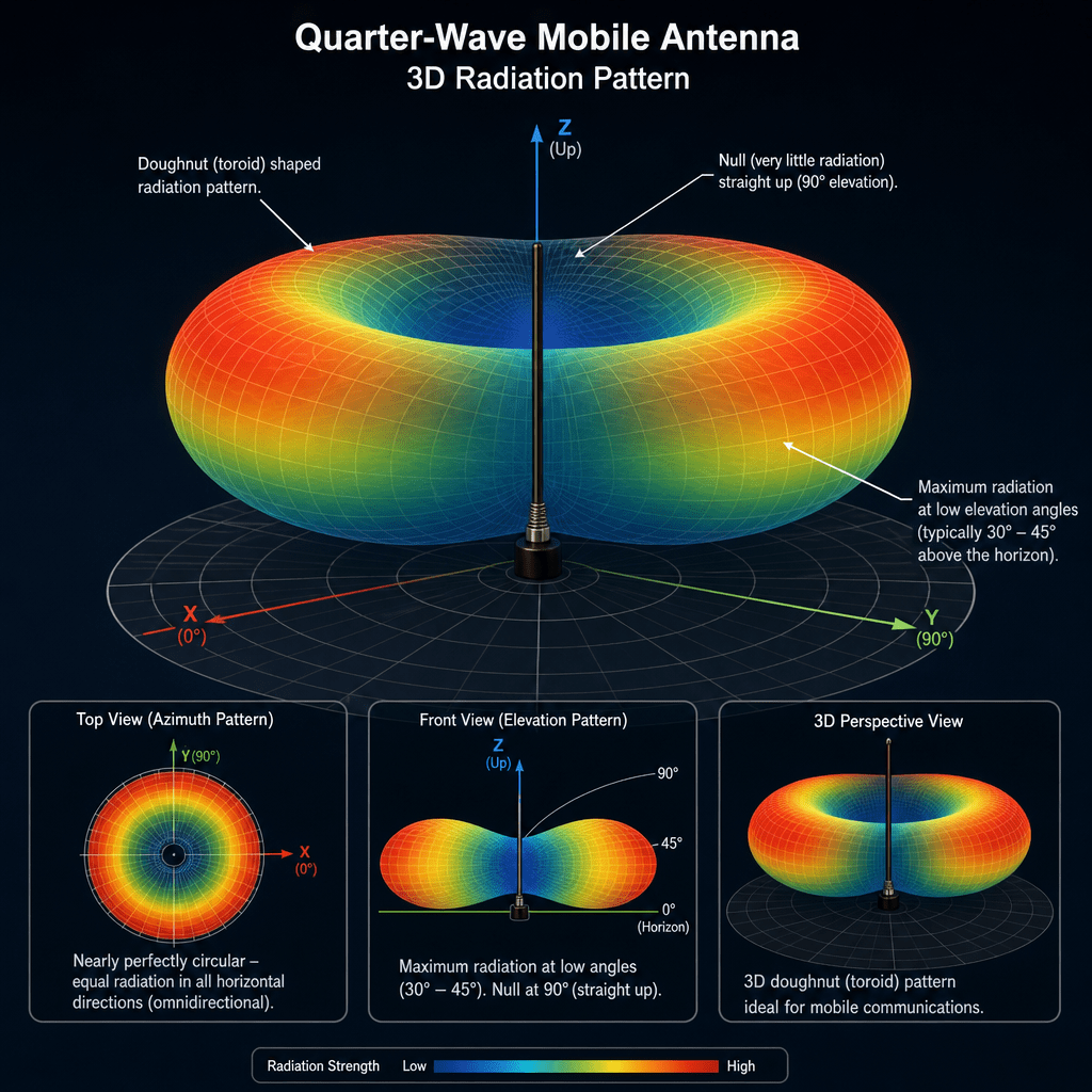
The use of the vehicle’s metal body as a ground plane is both practical and effective. It allows for a relatively short and sturdy antenna that can withstand the rigors of mobile use, such as wind, vibration, and weather exposure. The 1/4 wave antenna’s omnidirectional radiation pattern ensures that the signal is transmitted and received equally well in all directions around the vehicle, which is essential for mobile users who may be moving in any direction relative to other stations. This combination of efficiency, durability, and simplicity has made the 1/4 wave mobile antenna a mainstay in amateur radio, public safety, and commercial communication systems.
A 1/4 wave mobile antenna is commonly used on vehicles for VHF and UHF radio communication. Its length is set to one-quarter of the signal’s wavelength, allowing it to resonate efficiently. Mounted on a vehicle, the metal body acts as a ground plane, enhancing performance and shaping the radiation pattern to favor horizontal transmission. This design is both durable and practical, providing reliable, omnidirectional coverage for mobile users and making it a standard choice in many radio communication applications.
Features
The 1/4 wave mobile antenna is notable for its straightforward and robust construction, typically consisting of a single, straight metal rod. This simplicity not only makes the antenna easy to manufacture and install but also contributes to its durability, allowing it to withstand the physical stresses encountered during vehicle operation, such as wind, vibration, and exposure to the elements.
One of the key technical advantages of the 1/4 wave antenna is its natural impedance match to standard radio equipment. When mounted on a vehicle with a sufficiently large and conductive ground plane, the antenna’s impedance closely approximates 50 ohms, which is the standard for most transmitters and receivers. This inherent impedance match minimizes the need for additional matching components, ensuring efficient power transfer from the radio to the antenna and reducing signal loss due to reflections.
The radiation pattern of the 1/4 wave antenna is another feature that makes it particularly well-suited for mobile use. The antenna radiates energy equally in all directions around the vehicle in the horizontal plane, creating an omnidirectional pattern. This means that, regardless of the direction the vehicle is facing, the antenna will transmit and receive signals with similar effectiveness in every direction. The strongest radiation occurs at the horizon, which is ideal for communicating with other vehicles or base stations located at similar elevations. This combination of simple construction, effective impedance matching, and optimal radiation pattern has established the 1/4 wave mobile antenna as a reliable and popular choice for a wide range of mobile radio applications.
The 1/4 wave mobile antenna is valued for its simple, durable design—usually just a straight metal rod—which makes it easy to install and resilient to the rigors of vehicle use. Its natural impedance closely matches the standard 50 ohms of most radio equipment when paired with a good ground plane, ensuring efficient power transfer and minimal signal loss. The antenna’s omnidirectional radiation pattern provides consistent coverage in all directions, with maximum strength at the horizon, making it ideal for mobile communication with other vehicles or base stations. These features together make the 1/4 wave antenna a reliable and widely used choice for mobile radio systems.
5/8 Wave Mobile Antenna
The 5/8 wave mobile antenna represents an evolution in mobile antenna design, offering enhanced performance over the traditional 1/4 wave model. Its defining characteristic is its length, which is precisely five-eighths of the wavelength of the operating frequency—slightly longer than a half-wave antenna. This specific length is not arbitrary; it is chosen because it allows the antenna to produce a radiation pattern that is more tightly focused toward the horizon, rather than radiating energy upward or downward. This focus increases the effective range of communication, especially in the flat, horizontal environments typical for mobile radio use.
However, the increased length of the 5/8 wave antenna introduces certain electrical challenges. Unlike the 1/4 wave antenna, which naturally matches the standard 50-ohm impedance of most radio equipment when used with a proper ground plane, the 5/8 wave antenna does not inherently present the correct impedance. To address this, a matching network—usually a coil or inductor—is installed at the base of the antenna. This coil serves two purposes: it brings the antenna’s impedance into alignment with the radio system, ensuring efficient power transfer, and it helps maintain the desired current distribution along the antenna’s length, which is crucial for achieving the optimal radiation pattern.
The result is an antenna that, while slightly more complex in construction due to the need for the matching coil, delivers superior performance in many mobile applications. The 5/8 wave antenna’s ability to concentrate more energy at the horizon makes it especially popular among users who require maximum communication range from their vehicles, such as emergency services, commercial fleets, and amateur radio operators. Its design reflects a careful balance between physical length, electrical characteristics, and the practical demands of mobile communication.
The 5/8 wave mobile antenna is designed to be slightly longer than a half-wave, allowing it to focus more of its signal toward the horizon and thus extend communication range compared to the 1/4 wave antenna. Because its length does not naturally match the standard 50-ohm impedance, a matching coil is added at the base to ensure efficient power transfer and maintain the optimal radiation pattern. This makes the 5/8 wave antenna a bit more complex, but its superior performance and increased range make it a popular choice for users who need reliable, long-distance mobile communication.
Features
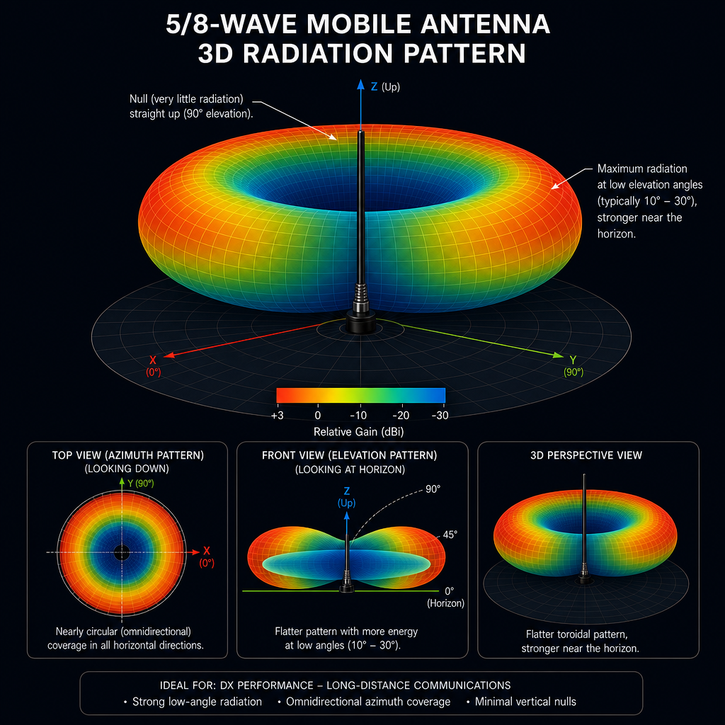
The 5/8 wave mobile antenna stands out for its ability to deliver higher gain compared to shorter designs, such as the 1/4 wave antenna. This increased gain is achieved by compressing the antenna’s radiation pattern, which means that more of the transmitted energy is directed outward along the horizon rather than being wasted in upward or downward directions. As a result, the antenna is able to provide a stronger, more focused signal over greater distances, making it especially valuable for mobile users who need to maintain reliable communication across wide, flat areas.
To achieve this performance, the 5/8 wave antenna requires a matching network, typically in the form of a coil or inductor at its base. This component is essential because, without it, the antenna’s impedance would not align with the standard 50-ohm input of most radio equipment. The matching coil not only ensures efficient power transfer from the transmitter to the antenna but also helps maintain the correct current distribution along the antenna’s length, which is crucial for producing the desired radiation pattern and maximizing the antenna’s effectiveness.
Despite being longer than a 1/4 wave antenna, the 5/8 wave design remains practical for vehicle installation. Its added length is generally manageable and does not pose significant challenges for mounting on cars, trucks, or other mobile platforms. This balance of increased performance, manageable size, and the need for a simple matching network has made the 5/8 wave antenna a popular choice among users who demand both range and reliability from their mobile radio systems.
The 5/8 wave mobile antenna offers higher gain by focusing more signal energy toward the horizon, resulting in greater communication range than shorter antennas. It requires a matching coil at the base to ensure proper impedance and efficient operation. Although slightly longer than a 1/4 wave antenna, its size remains practical for vehicles, making it a favored option for users who need both extended range and reliable performance in mobile radio systems.
Comparison and Summary
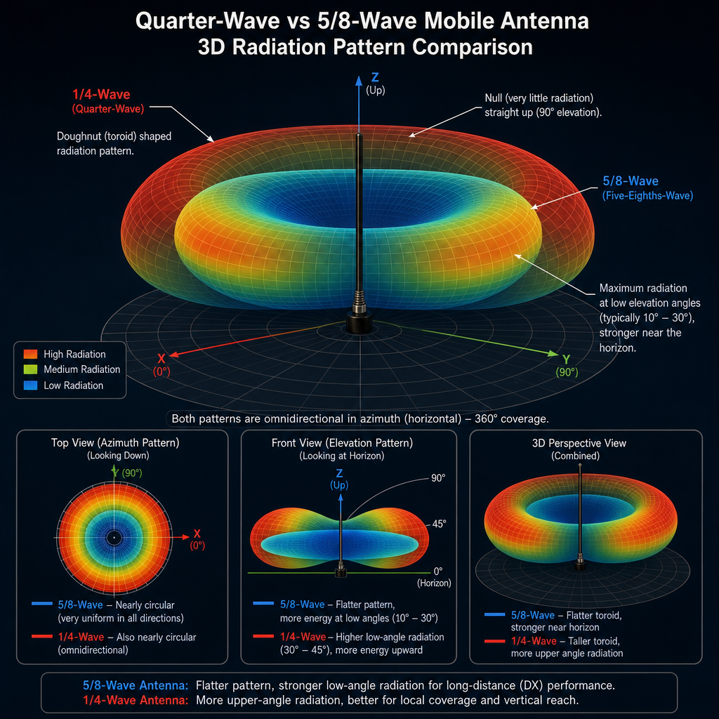
The 1/4-wave and 5/8-wave mobile antennas are both popular choices for vehicular radio communications, but they differ significantly in their design, radiation patterns, and optimal applications. A 1/4-wave antenna is typically a simple vertical whip whose length is one-quarter of the wavelength of the operating frequency. It relies on the vehicle’s metal body as a ground plane, creating an image antenna that helps form its radiation pattern. The 1/4-wave antenna produces a relatively broad, doughnut-shaped pattern with maximum radiation perpendicular to the antenna and less signal sent toward the horizon. This makes it a robust, forgiving choice for general mobile use, especially in urban or hilly environments where signals may need to bounce off buildings or terrain.
In contrast, the 5/8-wave antenna is longer—five-eighths of a wavelength—and is designed to compress the radiation pattern closer to the horizon. This results in a lower angle of radiation, which increases the effective range for ground-level communications by sending more energy outward rather than upward. The 5/8-wave antenna often requires a matching coil at its base to ensure proper impedance matching and efficient operation. Its flatter radiation pattern makes it ideal for use in open, flat areas such as highways or rural regions, where maximizing distance is more important than overcoming obstacles. However, the 5/8-wave antenna can be more sensitive to installation quality and ground plane size, and its increased length may be less convenient for mounting on vehicles. In summary, the 1/4-wave antenna is best for general-purpose, all-terrain use, while the 5/8-wave antenna excels in maximizing range over flat terrain.
Base Station Antennae
Overview
Base station antennae serve as the backbone of fixed radio communication systems, providing a stable and high-performance link for both transmitting and receiving signals over extended distances. Unlike mobile or handheld antennae, which must balance portability and durability with performance, base station antennae are typically installed in permanent locations such as radio repeater sites, emergency communication centers, or amateur radio operator homes. This fixed nature allows for much greater flexibility in terms of size, height, and design, enabling the use of larger and more efficient antenna structures that would be impractical on a vehicle or handheld device.
Because they are not constrained by the need for portability, base station antennae can be mounted on towers, rooftops, or dedicated masts, often at significant heights above ground level. This elevated placement is a major advantage, as it reduces obstructions and increases the line-of-sight range, allowing signals to travel farther and with less interference. The physical size of base station antennae can also be optimized for the specific frequency bands in use, which improves both efficiency and bandwidth.
In addition to their physical advantages, base station antennae can be tailored to the specific needs of the installation. Some are designed to be omnidirectional, radiating equally in all directions to provide broad area coverage, while others are highly directional, focusing energy in a particular direction to maximize range or minimize interference. The choice of antenna type, mounting height, and orientation is often determined by the communication goals of the station, the surrounding environment, and regulatory considerations.
Overall, base station antennae are engineered for maximum performance, reliability, and longevity. Their design reflects the priorities of fixed installations: consistent, high-quality communication, the ability to handle higher power levels, and the flexibility to adapt to a wide range of operational requirements. This makes them indispensable components in everything from public safety networks and commercial radio systems to amateur radio and emergency preparedness infrastructure.
Base station antennae are essential for fixed radio communication systems, offering stable and high-performance connections over long distances. Unlike portable or mobile antennae, they can be larger and mounted higher, which improves range and efficiency. Their design can be customized for omnidirectional or directional coverage, depending on the needs of the installation. Prioritizing reliability and adaptability, base station antennae are crucial for applications ranging from public safety and commercial networks to amateur radio and emergency communications.
Types and Features
Base station antennae come in a variety of types, each engineered to meet specific communication needs and environmental challenges. Among the most common are collinear, dipole, and Yagi-Uda antennae, each with distinct structural features and performance characteristics.
Collinear antennae are designed to maximize signal strength and coverage in the horizontal plane. They achieve this by stacking multiple radiating elements vertically, often separated by carefully tuned phasing sections. This vertical stacking causes the individual radiation patterns of each element to combine, resulting in a single, highly focused beam of energy directed outward along the horizon. The increased gain provided by collinear designs makes them ideal for base stations that need to cover large, flat areas—such as citywide repeater systems or commercial dispatch networks—where communication with users at ground level is the priority. The omnidirectional nature of collinear antennae ensures that signals are radiated equally in all directions around the antenna, providing consistent coverage without the need for precise aiming.
Dipole antennae, on the other hand, are among the simplest and most versatile designs. Consisting of two equal-length conductive elements aligned end-to-end, dipoles can be oriented either horizontally or vertically depending on the desired polarization and coverage pattern. When mounted horizontally, a dipole radiates most of its energy broadside to the antenna, making it suitable for local area coverage or as a building block for more complex antenna arrays. Vertical dipoles, meanwhile, offer omnidirectional coverage in the horizontal plane, similar to collinear designs but with less gain. The balanced nature of dipole antennae makes them easy to match to standard transmission lines, and their straightforward construction allows for reliable, long-term operation in a variety of environments.
Yagi-Uda antennae represent a more specialized approach, focusing on achieving high gain and strong directionality. A typical Yagi-Uda consists of a driven element (often a dipole), a reflector positioned behind it, and one or more directors placed in front. This arrangement causes the antenna to concentrate its energy in a single, narrow beam, greatly increasing signal strength in the desired direction while minimizing interference from unwanted sources. Yagi-Uda antennae are especially valuable for point-to-point communication, such as linking two distant base stations or targeting a specific repeater. Their directional nature also makes them useful for minimizing noise and interference in crowded radio environments.
Each of these antenna types offers unique advantages, and the choice among them depends on the specific requirements of the base station, including coverage area, desired range, and the need for directional versus omnidirectional communication. By selecting the appropriate antenna design, operators can optimize their systems for maximum efficiency, reliability, and performance.
Base station antennae come in several types, each suited to different communication needs. Collinear antennae stack elements vertically to boost gain and provide strong, omnidirectional coverage along the horizon, making them ideal for wide-area service. Dipole antennae are simple and versatile, offering either broadside or omnidirectional coverage depending on their orientation, and are easy to match and maintain. Yagi-Uda antennae are highly directional, focusing energy into a narrow beam for point-to-point links and minimizing interference. The choice of antenna depends on the station’s coverage goals and whether broad or targeted communication is needed, allowing operators to tailor performance to their specific requirements.
Advantages
Base station antennae offer significant advantages over their mobile and handheld counterparts, primarily due to their ability to be larger and more strategically positioned. Because these antennae are not limited by the constraints of portability or vehicle mounting, they can be constructed at lengths and with element configurations that are optimal for the frequencies in use. This increased physical size directly translates to higher efficiency, as the antenna can more effectively resonate with the intended signal, minimizing losses and maximizing the amount of energy radiated or received. Additionally, base station antennae are often installed on rooftops, towers, or dedicated masts, elevating them well above ground level and surrounding obstructions. This elevated placement not only extends the line-of-sight range—crucial for VHF and UHF communications—but also reduces the impact of local interference and signal blockages, resulting in clearer, more reliable communication over greater distances.
Another key advantage of base station antennae is their adaptability in terms of radiation pattern. Unlike mobile or handheld antennae, which are typically omnidirectional by necessity, base station designs can be tailored to the specific coverage requirements of the installation. For example, an omnidirectional antenna can be used to provide uniform coverage in all directions, ideal for serving a broad area or multiple users scattered around the station. Alternatively, highly directional antennae, such as Yagi-Uda or parabolic designs, can be employed to focus energy in a specific direction, greatly increasing signal strength and range in that direction while minimizing interference from unwanted sources. This ability to customize the radiation pattern allows operators to optimize their systems for a wide variety of scenarios, from citywide coverage to long-distance point-to-point links, ensuring that the base station delivers the best possible performance for its intended purpose.
Base station antennae outperform mobile and handheld types because they can be larger and placed higher, which boosts efficiency and extends range by reducing signal loss and interference. Their fixed installation allows for optimal design and positioning, while their radiation patterns can be customized for either broad or highly focused coverage. This flexibility ensures reliable, high-quality communication tailored to the specific needs of the station, whether serving a wide area or targeting distant locations.
Conclusion
Antennae serve as the essential bridge between electronic devices and the invisible world of electromagnetic waves, making them fundamental to the success of any radio communication system. The way an antenna is designed and implemented has a profound impact on how far and how clearly signals can be transmitted and received. For handheld radios, the primary concern is portability; the antenna must be compact and durable enough to accompany the user anywhere, even if this means sacrificing some efficiency and range. These compromises are necessary to ensure that the device remains practical for everyday use, allowing for reliable communication in a variety of unpredictable environments.
In contrast, mobile antennae, such as the 1/4 and 5/8 wave designs, are engineered to strike a balance between physical size and performance. Mounted on vehicles, these antennae take advantage of the vehicle’s metal body as a ground plane, which enhances their effectiveness. The 1/4 wave antenna offers simplicity and durability, while the 5/8 wave variant provides increased range by focusing more energy toward the horizon. Both types are tailored to the unique demands of mobile communication, where the direction and distance to other stations can change rapidly.
Base station antennae, freed from the constraints of portability, are optimized for maximum efficiency and coverage. Their larger size and elevated placement allow them to transmit and receive signals over much greater distances, and their design can be customized to provide either broad area coverage or highly focused, directional communication. This adaptability makes them indispensable for fixed installations, where consistent, high-quality communication is paramount.
Ultimately, a solid understanding of basic antenna theory and the strengths and limitations of different antenna types is crucial for anyone involved in radio communication. By selecting and deploying the right antenna for the application—whether handheld, mobile, or base station—operators can ensure reliable connections, clear signals, and effective communication across a wide range of scenarios.
Addendum: Basic Math for Antenna Theory
Antenna theory relies on several fundamental mathematical relationships that help determine the optimal size, performance, and matching of antennae for specific frequencies and applications.
The most basic calculation is the relationship between frequency () and wavelength (.) The wavelength of a radio wave is given by:
where c is the speed of light in a vacuum (approximately meters per second), and is the frequency in hertz (Hz). For example, at a frequency of 146 MHz (common in VHF radio), the wavelength is:
Antenna length is typically a fraction of the wavelength. For a 1/4 wave antenna, the length () is:
For a 5/8 wave antenna, the length () is:
These formulas allow you to calculate the physical length needed for resonance at a given frequency. As an example, for the national calling frequency, 146.52MHz (2.05m), 0.5m (19.7in) for the -wave antenna, resp. 1.28m (50.4in) for the -wave antenna.
Impedance matching is another key concept. Most radio systems are designed for a characteristic impedance of 50 ohms. The Standing Wave Ratio (SWR) is used to measure how well the antenna is matched to the transmission line and transmitter. SWR is calculated as:
where (the reflection coefficient) is:
Here, is the load (antenna) impedance and is the characteristic impedance of the transmission line (usually 50 ohms). An SWR of 1:1 indicates perfect matching, while higher values indicate increasing mismatch and reflected power.
Antenna gain is a fundamental concept in antenna theory and wireless communications, serving as a measure of how effectively an antenna directs or concentrates radio frequency energy in a specific direction, compared to a reference antenna. The reference is typically either an isotropic radiator, which is a hypothetical antenna that radiates power uniformly in all directions, or a half-wave dipole, which has its own characteristic radiation pattern.
The gain of an antenna is usually expressed in decibels (dB), a logarithmic unit that conveniently compresses the wide range of possible values into a manageable scale. The formula for antenna gain in decibels is:
In this equation, represents the power radiated by the antenna in the direction of interest, while is the power that would be radiated in that same direction by the reference antenna, given the same input power. The ratio inside the logarithm quantifies how much more (or less) power is radiated in a particular direction compared to the reference.
Antenna gain is not a measure of increased total power output; rather, it reflects the redistribution of radiated energy. An antenna with high gain focuses more energy in a specific direction, resulting in a stronger signal in that direction, but less energy in others. This is analogous to how a flashlight concentrates light into a beam, making it brighter in one direction compared to a bare bulb that emits light equally in all directions.
The choice of reference antenna affects the interpretation of gain values. When the reference is an isotropic radiator, the gain is called “isotropic gain” and is denoted as dBi. When the reference is a dipole, the gain is called “dipole gain” and is denoted as dBd. Since a dipole itself has a gain of about 2.15 dB over an isotropic radiator, dBd values are always lower than dBi values for the same antenna.
In practical terms, higher antenna gain is desirable when you want to transmit or receive signals over longer distances in a specific direction, such as in point-to-point wireless links or satellite communications. However, this comes at the expense of coverage in other directions, which may not be suitable for applications requiring omnidirectional coverage, like Wi-Fi access points in a home.
These basic equations form the mathematical foundation for designing, building, and evaluating antennae for any radio communication system. Understanding and applying them ensures that antennae are properly sized, matched, and optimized for their intended use.


Leave a Reply